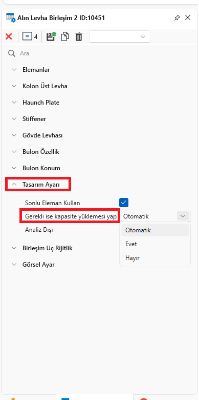
1) In the connection design, calculations should be made according to the capacity operating under the influence of earthquake. Apart from this, the design is made according to the load in connections that do not transfer moment or only receive load under effects such as wind.
In the general options of the program, there is a choice whether to calculate the combinations according to capacity, but this affects the entire model.
It is now possible to choose whether to perform capacity calculations on a combination basis.
3 options available
Automatic: The program makes automatic decisions based on the combination type.
No: No capacity calculation is made in the combination.
Yes: If it is a combination suitable for capacity calculation, capacity calculation is always made.

Click to View Image835 View(s)
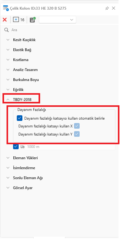
2) According to the 2018 earthquake regulation, element-by-element intervention can be made whether earthquake loads are multiplied by D or not in element design.
Automatic: The program decides itself according to the structure type
No: Earthquake loads on the relevant element are not multiplied by D
Yes: Earthquake loads on the relevant element are multiplied by D.

Click to View Image825 View(s)
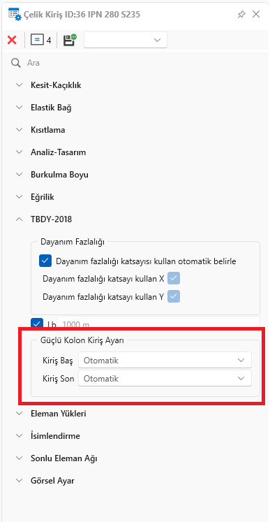
3) The option of whether the beams will be included in the element-based strong column calculation or not. If the program is connected to the column with a moment-transferring connection and requires earthquake regulations, checks such as the strong column-beam-column connection area are made on the column to which the relevant beam is connected. Unlike reinforced concrete, the connection where the beams are connected to the column plays an active role here. For example, this calculation would be meaningless since no moment would occur at the beam end that is connected to the column with a connection that does not transfer moment.
The program does this automatically according to the connection type, but for general intervention in intermediate stiffness and variation, the user can determine whether this control will be made on the column to which the beam is connected at the relevant end.

Click to View Image827 View(s)
4) External stiffener closure option in beam-to-beam connections.
5) The problem of incorrect display of Turkish characters in drawings and tables has been fixed. (There is no problem with dwg transfer)
6) In the English version, the expressions in the drawing tables were written in English.
7) The problem of connecting wide beams, which are important for the workshop, to overlap with other beams in the calculation model has been resolved.
8)Improved convergence problem display in AISC 360-16 direct analysis method.
9) The problem of not showing the axle text when drawing in reverse has been fixed.
10)For I profiles, EN 1993-1-1 6.2.8 (5) was adapted.
11)Composite beam shear stud unnecessary warning removed.
